
Fill and Sign the Vfw Meeting Minutes Template Form
Useful advice on finishing your ‘Vfw Meeting Minutes Template’ online
Are you fed up with the inconvenience of handling paperwork? Look no further than airSlate SignNow, the leading e-signature platform for individuals and businesses. Bid farewell to the tedious process of printing and scanning documents. With airSlate SignNow, you can effortlessly complete and sign documents online. Utilize the powerful features embedded within this easy-to-use and cost-effective platform and transform your method of document organization. Whether you need to sign forms or gather electronic signatures, airSlate SignNow manages it all effortlessly, needing just a few clicks.
Adhere to this comprehensive guide:
- Access your account or initiate a free trial of our service.
- Hit +Create to upload a file from your device, cloud storage, or our template repository.
- Open your ‘Vfw Meeting Minutes Template’ in the editor.
- Click Me (Fill Out Now) to prepare the document on your end.
- Add and assign fillable fields for other users (if necessary).
- Proceed with the Send Invite configurations to solicit eSignatures from others.
- Download, print your copy, or convert it into a reusable template.
No need to worry if you need to collaborate with others on your Vfw Meeting Minutes Template or send it for notarization—our platform provides you with all the tools necessary to accomplish these tasks. Register with airSlate SignNow today and elevate your document management to new levels!
FAQs
-
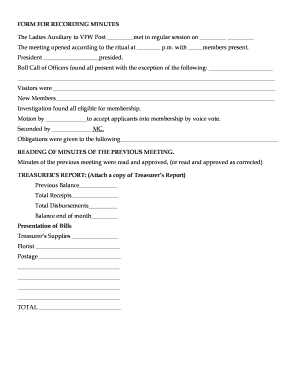
What is a Vfw Meeting Minutes Template?
A Vfw Meeting Minutes Template is a structured document designed to record the key details of a VFW (Veterans of Foreign Wars) meeting, including attendees, discussions, and decisions made. Using this template helps ensure that all important information is captured accurately and effectively, making it easier for members to review past meetings.
-
How can I obtain a Vfw Meeting Minutes Template using airSlate SignNow?
To obtain a Vfw Meeting Minutes Template with airSlate SignNow, simply visit our website and navigate to the template section. You can easily customize the template to fit your specific meeting needs, ensuring that all necessary details are included.
-
What features does the Vfw Meeting Minutes Template offer?
The Vfw Meeting Minutes Template offers several features including customizable fields, easy eSignature integration, and a user-friendly interface. These features streamline the process of documenting meetings, making it easier to share and manage minutes among members.
-
Is the Vfw Meeting Minutes Template suitable for large organizations?
Yes, the Vfw Meeting Minutes Template is suitable for large organizations, including VFW posts with numerous members. Its customizable nature allows you to tailor the template to accommodate larger groups and complex meeting agendas, ensuring that every voice is heard.
-
What are the benefits of using a Vfw Meeting Minutes Template?
Using a Vfw Meeting Minutes Template provides numerous benefits, including improved organization and clarity in meeting documentation. It helps ensure that all members are informed of discussions and decisions, fostering transparency and accountability within the organization.
-
Can I integrate the Vfw Meeting Minutes Template with other tools?
Absolutely! The Vfw Meeting Minutes Template can be easily integrated with various productivity and collaboration tools available in airSlate SignNow. This integration allows for seamless document sharing and enhances the efficiency of your workflow.
-
What is the pricing for accessing the Vfw Meeting Minutes Template?
The pricing for accessing the Vfw Meeting Minutes Template through airSlate SignNow is competitive and designed to provide cost-effective solutions for all types of organizations. You can choose from various subscription plans that suit your needs, with options for both individuals and teams.
Find out other vfw meeting minutes template form
- Close deals faster
- Improve productivity
- Delight customers
- Increase revenue
- Save time & money
- Reduce payment cycles
