Establishing secure connection… Loading editor… Preparing document…
Navigation

Fill and Sign the California Notary Resignation Letter Sample Form
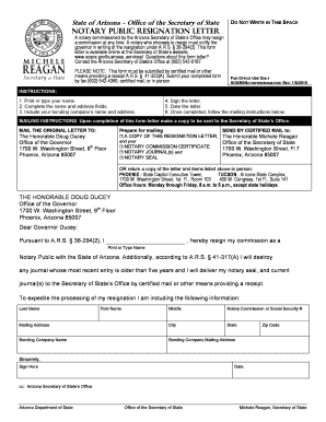
Fill and Sign the California Notary Resignation Letter Sample Form

How it works

Open the document and fill out all its fields.
Apply your legally-binding eSignature.
Save and invite other recipients to sign it.

Rate template

4.6
40 votes
FINAL DRAFT A BEGINNERS GUIDE TO THE OPERATION OF YS FUEL CONTROL SYSTEMS Introduction Few seasoned campaigners will need convincing of the benefits of pressurised fuel delivery systems when it comes to coping with the rigours of modern F3A schedules. As far back as the 70’s, Terry Cooper stole a march on other competitors by fitting his OPS 60 with a separate TK Regulator to supply fuel at positive pressure to a large bore aftermarket carburettor. Not only did this provide Terry’s famous Bulldog design with significantly more power than the competition, but it also provided much greater consistency of engine performance than was common at the time. Other well-recognised benefits included the ability to mount fuel tanks further back in the fuselage, thereby minimising the variation in CG as fuel was drawn from the tank. Although others were quick to latch on to the advantages, it was some time before a reliable purpose designed aerobatic engine became widely available in the UK. One of the earliest and most successful units was the YS60, a short stroke 2-cycle engine, used to great effect by Ken Binks and other top GBRCAA competitors back in the late 80’s. This used an integrated regulator to supply fuel at positive pressure to a wide bore butterfly style front induction carburettor. As enduring evidence of its success, the same basic design is still used in the current YS 45 and 91 2 strokes, much loved by many helicopter pilots. The underlying design principles were also incorporated into the early YS 4-strokes, and with one or two minor tweaks, still survive in the current 4-stroke range including the highly successful YS63, YS110 and YS140 FZ’s (Sport and L). Old hands will already be highly familiar with the operation of the YS system – a topic covered in previous issues of the magazine. This article is not for you! However as more top fliers migrate to the latest version of the YS140 – the DZ ‘Dingo’ – many of the older units will be finding their way into less experienced hands. Set up correctly, most of these earlier YS designs are as close to trouble free as you can get. But as with most more complex systems, it is worth investing time in getting to grips with the basic principles before tweaking the controls! Sadly, it is still all too common for newcomers to be told to “turn the regulator adjustment this way” when they would be better advised to turn it in the opposite direction or not touch it at all! This article therefore is mainly intended as a reference for those newcomers who wish to understand the basic theory which underpins the practice. The original YS Pressurised Fuel Delivery System As a competitor in the late 80’s I was fortunate to own several of the early YS60 2 strokes, both rear (RE) and side (SE) exhaust. Although they all proved to be highly reliable, I succumbed to temptation and stripped one of the older units down to get a better feel for how it operated! A computerised version of my original freehand sketch is reproduced as Fig 1. Throttle Up Fuel at regulated pressure Pr Main NV Tapered Metering Slot Fuel to inlet venturi Throttle Down Crankcase Pressure Pc To Tank NRV Pc Pr k Silicon Diaphragm Control Valve Spring From Tank Typically 6 to 9 psi Brass Adjustment Screw Fig 1: Diagrammatic representation of early YS pressure regulator system Although originally designed for 2-strokes, the same basic principles of pressure regulation were also used in the early range of YS 4-strokes. A small hole under the front housing of the crankcase, transferred crankcase pressure, Pc, through a non-return valve (NRV) to the tank. Typical operating pressure for the tank was 6 to 9 psi, hence the requirement to select a robust tank with a good pressure tight bung. Fuel from the tank entered the bottom chamber of a 3-chamber pressure regulator before being admitted to a central chamber via a regulating control valve. Fuel at regulated pressure Pr in the centre chamber was then fed through the main needle valve before entering the inlet venturi via a carefully machined “tapered metering slot” in the main barrel of the carburettor. The regulated pressure Pr was preset by adjusting the compression of the spring sitting under the control valve, via the brass adjustment screw in the regulator base. Any fall in the regulated pressure, caused the regulator diaphragm to move downwards, opening the control valve, and restoring the regulated pressure to its setpoint. Assuming: Pc = Crankcase/tank pressure Pr = Regulated pressure to main needle valve/spray bar a = Cross sectional area of diaphragm k = Upwards force due to spring compression Then at equilibrium, the forces acting on the diaphragm could be summarised as: Downwards Force (Pc x a) = Upwards Force (Pr x a + k) Expressed in a different form the equation becomes: Regulated Pressure (Pr) = Crankcase Pressure (Pc) – k/a Note that in order to obtain an increase in the regulated pressure (i.e. a richer mixture) it is necessary to reduce k (the spring compression) by turning the brass adjustment screw counter clockwise. This is the precisely opposite to the normal operation of the more common form of 2 chamber pressure regulator (e.g. Perry Pump), in which the outlet pressure is increased by turning the adjustment screw clockwise. Failure to appreciate the difference in the operation of 3 chamber and 2 chamber regulators is one of the most common reasons for YS engines being set up incorrectly! Most of these earlier engines were delivered with the regulators “factory set” and had no form of separate slow running adjustment other than the throttle stop itself. In practice however, it was often necessary to make small adjustments to the regulator setting to alter the slow speed mixture through a small increase or decrease in the regulated pressure (Pr). This in turn caused a small variation in the high-speed mixture and a little bit of iteration was sometimes required to get the engines fully dialled in. However once properly set up and operated, the system was virtually trouble free and it was common for users to go for a full season without needing any adjustments to the fuel settings. In later designs of YS 4-stoke, a small adjusting screw was incorporated in the end of the throttle barrel to further improve the operation of earlier designs by providing a separate adjustment for slow/mid speed running. In practice this operated as an air bleed, with the valve being turned clockwise to richen and counter clockwise to lean out the low speed mixture (i.e. opposite effect to the high speed needle). In these later designs, the brass regulator screw was “genuinely” factory set (approximately flush with the regulator housing) and was best left in that position! Enter the YS 140 DZ “Dingo” In 2002, to cater for the ever-increasing requirements for top-level performance, YS introduced the new YS140 Dingo. This differed from all previous YS engines in using direct fuel injection into the cylinder head and a positive displacement pump as the means of fuel transport. The operation of the Dingo pump mechanism was covered in detail in Keith Jackson’s excellent article in GBRCAA May/June 2003 Magazine. For completeness, a simplified version of Keith’s sketch is shown in Fig 2 below: NRV Supply from tank NRV To needle valve/throttle body assembly Regulator Housing Positive Displacement Pump Diaphragm Pressure control kickback line Spring Crankcase reference pressure Brass Adjustment Screw Fig 2: Simplified diagram of fuel delivery system for YS 140 DZ 'Dingo' In the “Dingo”, the regulated pressure to the needle valve assembly is controlled by adjusting the amount of “kickback” from the delivery to the suction of the positive displacement pump. Turning the Brass Adjustment Screw clockwise, decreases the amount of kickback and increases the delivery pressure thus richening the mixture (i.e. the opposite effect to the earlier pressurised tank designs!) Note also, that when filling the tank it is possible to pass fuel straight through the pump and its inlet and outlet NRV’s into the needle valve assembly. Hence the need to avoid engine flooding by blocking or disconnecting the pump suction line when refuelling the tank. (In the earlier designs – see Fig 1 - loss of crankcase pressure with the engine stopped caused the control valve to move upwards effectively blocking the delivery from the tank.) Summary For those less keen on theory, the correct means of adjusting YS engines can be summarised as follows: ENGINE TYPE 2-Strokes Early 4-strokes Later 4-strokes 140DZ “Dingo” REGULATOR SCREW Counter clockwise to richen and vice versa. (Small adjustments only). Counter clockwise to richen and vice versa. (Small adjustments only). Leave factory set. (Flush with regulator body) Clockwise to richen and versa. LO SPEED NEEDLE HI SPEED NEEDLE Not fitted Counter clockwise to richen and vice versa. Not fitted Counter clockwise to richen and versa. Clockwise to richen and vice versa. Counter clockwise to richen and versa. See Regulator Adjustment Counter clockwise to richen and versa. Properly set up, YS fuel delivery systems are amongst the most reliable available. I hope that this short article will be of some help – particularly to beginners - in aligning the theory with the practice and helping them get the best from their equipment. The pulsating delivery from piston operated positive displacement pumps means that their delivery pressure is notoriously difficult to regulate. Despite the undoubted success of the 140 “Dingo”, rumours are already circulating that the soon to be introduced 160DZ will incorporate yet further improvements to the pump control system. That is the nature of continuous development. Don’t be too surprised if the Table needs an additional row including in the not too distant future. Bob Wasson GBR/CAA 2004 Appendix 1 Plumbing for YS Dingo PLUMBING FOR YS DINGO Fuel Dot Non return Valve To tank vent From foam clunk Filter External Fuel Clamp Fuel Dot

Useful suggestions for preparing your ‘California Notary Resignation Letter Sample’ online

Are you fed up with the burden of handling paperwork? Look no further than airSlate SignNow, the premier eSignature solution for individuals and small to medium-sized businesses. Bid farewell to the monotonous task of printing and scanning documents. With airSlate SignNow, you can easily complete and sign documents online. Utilize the robust features embedded in this user-friendly and budget-friendly platform and transform your method of handling paperwork. Whether you need to authorize documents or gather electronic signatures, airSlate SignNow manages it all effortlessly, with just a few clicks.

Follow this detailed guide:

  1. Sign in to your account or initiate a complimentary trial with our service.
  2. Click +Create to upload a document from your computer, cloud storage, or our form repository.
  3. Open your ‘California Notary Resignation Letter Sample’ in the editor.
  4. Click Me (Fill Out Now) to finalize the form on your end.
  5. Add and designate fillable fields for other participants (if needed).
  6. Proceed with the Send Invite settings to solicit eSignatures from others.
  7. Save, print your version, or convert it into a reusable template.

Don't be concerned if you need to collaborate with your team on your California Notary Resignation Letter Sample or send it for notarization—our platform offers everything required to accomplish such tasks. Sign up with airSlate SignNow today and elevate your document management to new levels!

Here is a list of the most common customer questions. If you can’t find an answer to your question, please don’t hesitate to reach out to us.

Need help? Contact Support
California Notary application PDF
Notary form California
State of California notary application status
Notary name change California
Notary Certificate California
Notary renewal California cost
California Notary search
California Notary acknowledgement example
Sign up and try California notary resignation letter sample form
  • Close deals faster
  • Improve productivity
  • Delight customers
  • Increase revenue
  • Save time & money
  • Reduce payment cycles