eSigning WPT Made Easy
Award-winning eSignature solution


Get the robust eSignature features you need from the company you trust
Select the pro service created for professionals
Set up eSignature API quickly
Collaborate better together
Esigning wpt, within minutes
Decrease the closing time
Keep sensitive data safe
See airSlate SignNow eSignatures in action


airSlate SignNow solutions for better efficiency
Our user reviews speak for themselves


Why choose airSlate SignNow
-
Free 7-day trial. Choose the plan you need and try it risk-free.
-
Honest pricing for full-featured plans. airSlate SignNow offers subscription plans with no overages or hidden fees at renewal.
-
Enterprise-grade security. airSlate SignNow helps you comply with global security standards.

Your step-by-step guide — esigning wpt
Employing airSlate SignNow’s eSignature any business can accelerate signature workflows and eSign in real-time, providing a greater experience to customers and employees. Use esigning WPT in a few simple steps. Our mobile apps make working on the move achievable, even while offline! eSign contracts from any place worldwide and close up trades in no time.
Follow the step-by-step guideline for using esigning WPT:
- Sign in to your airSlate SignNow profile.
- Find your record in your folders or upload a new one.
- Open up the template and edit content using the Tools list.
- Place fillable boxes, type text and eSign it.
- Add several signees by emails configure the signing sequence.
- Choose which individuals can get an completed copy.
- Use Advanced Options to restrict access to the record and set an expiry date.
- Click on Save and Close when finished.
Moreover, there are more innovative tools available for esigning WPT. List users to your common work enviroment, view teams, and keep track of cooperation. Millions of consumers all over the US and Europe agree that a system that brings people together in a single unified enviroment, is exactly what organizations need to keep workflows working effortlessly. The airSlate SignNow REST API enables you to integrate eSignatures into your application, internet site, CRM or cloud storage. Check out airSlate SignNow and enjoy quicker, easier and overall more effective eSignature workflows!
How it works
airSlate SignNow features that users love


See exceptional results esigning WPT made easy

How to fill in and sign a PDF online
Try out the fastest way to esigning WPT. Avoid paper-based workflows and manage documents right from airSlate SignNow. Complete and share your forms from the office or seamlessly work on-the-go. No installation or additional software required. All features are available online, just go to signnow.com and create your own eSignature flow.
A brief guide on how to esigning WPT in minutes
- Create an airSlate SignNow account (if you haven’t registered yet) or log in using your Google or Facebook.
- Click Upload and select one of your documents.
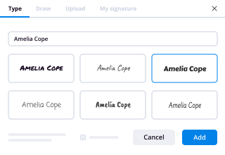
- Use the My Signature tool to create your unique signature.
- Turn the document into a dynamic PDF with fillable fields.
- Fill out your new form and click Done.
Once finished, send an invite to sign to multiple recipients. Get an enforceable contract in minutes using any device. Explore more features for making professional PDFs; add fillable fields esigning WPT and collaborate in teams. The eSignature solution supplies a safe process and runs according to SOC 2 Type II Certification. Ensure that all your records are protected so no one can edit them.


How to eSign a PDF template in Google Chrome
Are you looking for a solution to esigning WPT directly from Chrome? The airSlate SignNow extension for Google is here to help. Find a document and right from your browser easily open it in the editor. Add fillable fields for text and signature. Sign the PDF and share it safely according to GDPR, SOC 2 Type II Certification and more.
Using this brief how-to guide below, expand your eSignature workflow into Google and esigning WPT:
- Go to the Chrome web store and find the airSlate SignNow extension.
- Click Add to Chrome.
- Log in to your account or register a new one.
- Upload a document and click Open in airSlate SignNow.
- Modify the document.
- Sign the PDF using the My Signature tool.
- Click Done to save your edits.
- Invite other participants to sign by clicking Invite to Sign and selecting their emails/names.
Create a signature that’s built in to your workflow to esigning WPT and get PDFs eSigned in minutes. Say goodbye to the piles of papers sitting on your workplace and start saving time and money for extra crucial activities. Choosing the airSlate SignNow Google extension is a smart convenient option with lots of benefits.


How to eSign an attachment in Gmail
If you’re like most, you’re used to downloading the attachments you get, printing them out and then signing them, right? Well, we have good news for you. Signing documents in your inbox just got a lot easier. The airSlate SignNow add-on for Gmail allows you to esigning WPT without leaving your mailbox. Do everything you need; add fillable fields and send signing requests in clicks.
How to esigning WPT in Gmail:
- Find airSlate SignNow for Gmail in the G Suite Marketplace and click Install.
- Log in to your airSlate SignNow account or create a new one.
- Open up your email with the PDF you need to sign.
- Click Upload to save the document to your airSlate SignNow account.
- Click Open document to open the editor.
- Sign the PDF using My Signature.
- Send a signing request to the other participants with the Send to Sign button.
- Enter their email and press OK.
As a result, the other participants will receive notifications telling them to sign the document. No need to download the PDF file over and over again, just esigning WPT in clicks. This add-one is suitable for those who choose working on more valuable aims instead of burning time for nothing. Enhance your daily compulsory labour with the award-winning eSignature solution.


How to sign a PDF file on the go without an mobile app
For many products, getting deals done on the go means installing an app on your phone. We’re happy to say at airSlate SignNow we’ve made singing on the go faster and easier by eliminating the need for a mobile app. To eSign, open your browser (any mobile browser) and get direct access to airSlate SignNow and all its powerful eSignature tools. Edit docs, esigning WPT and more. No installation or additional software required. Close your deal from anywhere.
Take a look at our step-by-step instructions that teach you how to esigning WPT.
- Open your browser and go to signnow.com.
- Log in or register a new account.
- Upload or open the document you want to edit.
- Add fillable fields for text, signature and date.
- Draw, type or upload your signature.
- Click Save and Close.
- Click Invite to Sign and enter a recipient’s email if you need others to sign the PDF.
Working on mobile is no different than on a desktop: create a reusable template, esigning WPT and manage the flow as you would normally. In a couple of clicks, get an enforceable contract that you can download to your device and send to others. Yet, if you really want an application, download the airSlate SignNow mobile app. It’s comfortable, fast and has a great design. Take advantage of in seamless eSignature workflows from your workplace, in a taxi or on a plane.

How to sign a PDF file using an iPhone
iOS is a very popular operating system packed with native tools. It allows you to sign and edit PDFs using Preview without any additional software. However, as great as Apple’s solution is, it doesn't provide any automation. Enhance your iPhone’s capabilities by taking advantage of the airSlate SignNow app. Utilize your iPhone or iPad to esigning WPT and more. Introduce eSignature automation to your mobile workflow.
Signing on an iPhone has never been easier:
- Find the airSlate SignNow app in the AppStore and install it.
- Create a new account or log in with your Facebook or Google.
- Click Plus and upload the PDF file you want to sign.
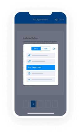
- Tap on the document where you want to insert your signature.
- Explore other features: add fillable fields or esigning WPT.
- Use the Save button to apply the changes.
- Share your documents via email or a singing link.
Make a professional PDFs right from your airSlate SignNow app. Get the most out of your time and work from anywhere; at home, in the office, on a bus or plane, and even at the beach. Manage an entire record workflow seamlessly: build reusable templates, esigning WPT and work on PDF files with business partners. Turn your device right into a powerful business instrument for closing contracts.

How to sign a PDF taking advantage of an Android
For Android users to manage documents from their phone, they have to install additional software. The Play Market is vast and plump with options, so finding a good application isn’t too hard if you have time to browse through hundreds of apps. To save time and prevent frustration, we suggest airSlate SignNow for Android. Store and edit documents, create signing roles, and even esigning WPT.
The 9 simple steps to optimizing your mobile workflow:
- Open the app.
- Log in using your Facebook or Google accounts or register if you haven’t authorized already.
- Click on + to add a new document using your camera, internal or cloud storages.
- Tap anywhere on your PDF and insert your eSignature.
- Click OK to confirm and sign.
- Try more editing features; add images, esigning WPT, create a reusable template, etc.
- Click Save to apply changes once you finish.
- Download the PDF or share it via email.
- Use the Invite to sign function if you want to set & send a signing order to recipients.
Turn the mundane and routine into easy and smooth with the airSlate SignNow app for Android. Sign and send documents for signature from any place you’re connected to the internet. Create good-looking PDFs and esigning WPT with just a few clicks. Come up with a flawless eSignature workflow with just your smartphone and increase your total productiveness.
Get legally-binding signatures now!
What active users are saying — esigning wpt


Esigning wpt
hi I'm Sabine Yaakov this presentation is entitled wireless power transfer circuit theory limitations of the classical design now a wireless power transfer system consists of two antennas one of the transmitter connected to the driver here and then there is the receiving antenna connected to receiver which has a rectifier some other electronics in it in it in order to extract the power from the antenna now the transfer of energy from the transmitter to the receiver is based on a inductive or magnetic transfer and that is that the transmitter is generating a magnetic flux which is then penetrating through the receiving antenna and in therefore generating a voltage here which actually transferred the power to the receiver now unfortunately part of this flux is actually not common to the tool and it's sort of closed here around the transmitter so therefore not all the flux is actually moved to the receiver and in order to quantify it we have this coupling coefficient term such that K times the total flux is the common or the flux which is common to both the transmitter every receiver while 1 minus K flux total flux is the part which is not common and the stray flux here around the transmitter itself now the way to analyze the circuit like this a classical way textbook approach would be by mutual inductance we have two inductor these are the antennas and in order to optimize the circuit would see it later we put a capacitors primary secondary and then we have unfortunately the pathetic resistances of the wire of the antennas and interconnection and then obviously we have this mutual inductance which is equal to K times the square root of the product of these inductances now in order to simplify the presentation here and the expression I'm assuming the diesel are equal this is not losing any generality there's just simplifying the discussion now RL actually represent the load now loads are not resistors usually they are active circuit like with a rectifier and a charger or switch mode converter but it is customary to replace the actual and nonlinear load by a equivalent code so called our AC load which represents the power consumption the power consumption of the load so this is why I am going to use this R sub M as representing the load now the method for analyzing circuit like this can be based on actually separating the two coupled pairs and then introducing a dependent dependent voltage sources defined by j omega m i2 which is current secondary in J Omega M i1 are of the primary these inductors are no more coupled this both these voltage sources or dependent voltage sources are actually taking care of the original coupling here so the current in the secondary is the voltage divided by the total resistance okay total resistance here or I should say total impedance here is ISA s which is equal to the sum of these components and therefore the voltage source at the secondary which is J Omega M times i2 and i2 is this value and since we have products of two J's and there is a minus here this becomes resistive this part and then divided by this of s and I 1 so this voltage source actually is this value here so we can call this as the pins the values the units are really ohms because this is M square divided by ohm and this a big sort of they reflected impedance to the primary and the voltage force is this reflected resistance times I won so in fact the voltage source can be as shown here can be replaced by any pittance Z sub R heart which is equal to this value here I've shown here Omega K here have the two inductance s divided by this V sub s and this is the value here this is the total impedance here now obviously you know to get a maximum current in the primary you'd like these are to be as small as possible and this can be done by running the system at residence such that Z sub s in this sub s these two components will cancel each other the impedances if it is at resonance and you'll be left just be with the resistive component so this is actually what is done the components go back for seconds of these two reactive elements else' basis of s and these two are chosen such that they are equal to the excitation frequency of the excitation frequency is adjusted to death and therefore we have now a resistive circuit circuit none of the reactive element is shown anymore we have just the parasitic resistors they reflected this is now a resistance R L Prime into sum of these two the same thing goes for the secondary we have this positive resistance and the actual RAC or they register which represent the load now the power that will be delivered to the load is I 2 pi sub 2 squared times the load okay now I 2 squared is of course the voltage divided by the total impedance and this voltage is a function of the current at the primary so we end up with this expression I 1 squared times this expression and then I have to correct it for the fact that I've actually calculated the power for the total branch and to get just this portion here I have to do multiply it by this ratio let's not worry about this because at high efficiency this is approaching 1 so let's talk about this part here now what we see here is very interesting that we see that this resistor here this reflected register actually represent the power consumption of the system because we see that I squared I 1 square times this one is indeed the power that is delivered to the load so this actually simplifies matter because then we can not just look at the primary in here and optimize the circuit in terms of this like that value in terms of the efficiency and the power transfer so this is what we are going to do now we then have the problem that we have a source we have a prosthetic resistance and we have this reflected resistance so for high efficiency we would like to have this term much larger than this pathetic resistance that is shown here this one we'd like to have it much much larger than this one and the same thing goes for the secondary we like this resistor to be larger than this pathetic resistance now there is not much we can do here because this is what we choose RL that's it so here is where we can concentrate and understand what's going on and maybe optimize the system by looking at the primary so from here we find that Arab Prime has to be much smaller than this value this all this is known this is the operating conditions and this is also the part that ik resistance now how small should it be it really depends on the efficiency that we are looking for and the efficiency is the ratio I mean this is the primary efficiency of the primary it is the dis resistance divided by the resistance plus the paralytic resistance and therefore this we can sort of quantize this this relationship and say that given a certain efficiency we would like this value to be about this value well this is the efficiency / 1 - efficiency time to depart attic resistance or this is now expressed as our prime has to be for this target efficiency has to be about this value all of these are known is their running frequency mutual inductance prosthetic resistance and the target efficiency so let's have a look now at some green numbers here let's assume that we are running the system at 150 kilo Hertz these two inductances are 20 micro Henry positive resistances are 100 million point 1 ohm and let's do the calculation for a coupling coefficient of 0.5 now first thing I'm calculating Omega M which turns out this is the 2 point 1 point 5 10 to the 5th this is the one frequency and Kate it comes up to be 10 ohm square it's 100 ohm square so we want to keep this relationship and taking a 90 percent the target then we find that this should be around ten times the resistance the positive resistance and I find that they are a prime that if the total resistance here should be around 100 this is for K point five four point eight it comes up to be 250 it's a different number now what about the power that we can transfer now power is as we have said approximately being divided square divided by this resistance well if you like to have it more accurate you have to multiply by the efficiency actually taking into account the losses here in our case it turns out to be mean over one times the efficiency so say one vote will sort of will be a little bit less than one part for one vote excitation from here we find that the power is proportional to our n because the larger there are end the smaller would be this value and the larger will be P out so we can to put her adhere to the nominator and see that the larger the power the larger is our LD larger the power but what about losses now we know that the smaller is this value the larger would be the losses or we were like this value to be large and therefore the loss is a sort of 1 over this value and again the losses seem to be proportional to our rap so here's the problem we are locked here if we increase our L we increase the power but the loss is increased so the efficiency will go down and vice versa so there is a fine area here's an area that can work with fairly high power and fairly high efficiency and if you move from it you are in a problem then there is a question of the quality factor the quality factor of this circuit with the inductor and capacitor is the this series resonant network will be the Omega L over R I'm neglecting the pathetic resistance and since this is omega L this is also mega n lighter I end up with this and in this particular case we are now looking at this numerical situation we find that the Q is around 10 this is fairly high this means that small deviation and the excitation frequency or the tuning will move us from the optimum point so this is another issue that one has to take into account so let's have a look now at some of the simulation of this circuit for the particular parameters that I've taken as an example so here we have the inductances the this capacitor were chosen to match it to a 150 kilo Hertz this is the running frequency here and here is our is the parameter the losses says what has me do here in 100 milliohms here so for K point 5 the value we've chosen we know that the sort of optimum value is 100 ohm we see the indeed the efficiency is as we expected or we a target that it's about 0.9 and the power as we have actually predicted Li is approaching one ground so this is really very consistent with what we have said now what happens if we are moving from this optimal point sorry the case that I've run it for 100 oh this is the nominal value and then 1k so let's look at here first the 1k brings up a much higher power this is two and a half what has compared to one run but see the efficiency very bad it's point five so you see that increasingly with the store is indeed increasing the power as we expected but also increasing them also so therefore the efficiency went down quite a bit now I've also added a resistor of 10 ohms now the efficiency is very good very excellent or not 100% but the power that we can get is very low here it is and I expanded scale here so this is for 10 on the efficiency this is the 100 ohm which is 2.9 this is almost 100% but the power we can get is very very low as compared to only few milli watts 100 milliwatts perhaps as compared to what we actually lower them that as compared to what we have here so we see that indeed the system is very very sensitive to the value of the resistor given the operating point the frequency the inductances and of course most important is the coupling coefficient this is taking into account the coupling coefficient and now what happens if the coupling coefficient is changing so I'm keeping now the resistor to be 100 ohms and changing the coupling coefficient 0.2 0.4 in point 8 now the nominal value for which we have chosen 100 ohm was 0.5 okay so what we see here is again a variation 4.4 which is close to 0.5 we see pretty good efficiency pretty good efficient this is the point 8c and the power is not so bad it's also about one what is the point for now what happens with the point eight this is actually very good coupling much better but again since it is not optimized we have indeed a a higher efficiency to 0.82 high efficiency almost one artisan but power level is very low and for the point two we have a lower efficiency but higher power so we have much higher power but lower efficiency so again we see that once you move from this optimal point you get into trouble so what can be done one way to go if people have shown in the number of papers is to do impedance matching this could be done by a passive network such that the impedance that the system would see would be changed to the optimal one or by a active like switch mode converter which can also reflect a resistance which is different from the actual resistance so what are the conclusions here we see that there is a very large load dependence here and one have to bear in mind that no more loads practice are not resistors they are say constant power loads and then the extra resistance is the power divided by hi square for the hour battery charging and in this case they resistance is something like the voltage of the battery divided by the current times some constant so we don't deal with resistors as loads we deal with active circuitry which has a variable reflected load so there might be a need in order to optimize the system for an impedance matching between the actual load you have and the optimum load for the system especially if indeed you are under changes of the coupling coefficient that is the distance so the distance is really a major player here and the larger the distance the more complicated becomes the situation and you'd expect the lower power transfer and lower efficiency and then there is the issue of the high Q which means that a deviation of frequency and components might actually move you from the optimal point so this brings me to the end of this presentation I hope you found it interesting and perhaps it will be useful to you in the future
Show moreFrequently asked questions
How do I eSign a document before sending it?
How do I sign a PDF contract?
How can you sign your name on a PDF?
Get more for esigning WPT made easy
- Print signature service Audit Proposal Template
- Prove email signature Wedding Contract
- Endorse eSign Business Gift Certificate
- Authorize digital sign Land Contract Form
- Anneal signatory Buy Sell Agreement
- Empower electronically signed Summer Camp Volunteer Pastor Application Template
- Try digisign Press Release Email
- Add Commercialization Agreement initial
- Send Photography Proposal Template signature
- Fax CCW Certificate email signature
- Seal Hardship Letter digital signature
- Password Sales Agreement electronically signed
- Pass Plumbing Contract Template byline
- Renew Deed of Trust esign
- Test Web Development Progress Report signature block
- Require OPM 71 Form signature service
- Send gawker eSign
- Accredit undersigned initials
- Compel heir signatory
- Void Design Quote Template template electronically sign
- Adopt log template countersignature
- Vouch Colorado Rental Agreement template digital signature
- Establish Printing Quotation template signed
- Clear Compromise Agreement Template template digi-sign
- Complete Camper Health History template esign
- Force Real Estate Agency Agreement Template template digital sign
- Permit Power of Attorney Form template initial
- Customize Wedding Photography Contract Template template signature