Warrant eSigning with airSlate SignNow
Award-winning eSignature solution


Do more on the web with a globally-trusted eSignature platform
Remarkable signing experience
Reliable reports and analytics
Mobile eSigning in person and remotely
Industry rules and compliance
Warrant esigning, faster than ever before
Helpful eSignature add-ons
See airSlate SignNow eSignatures in action


airSlate SignNow solutions for better efficiency
Our user reviews speak for themselves


Why choose airSlate SignNow
-
Free 7-day trial. Choose the plan you need and try it risk-free.
-
Honest pricing for full-featured plans. airSlate SignNow offers subscription plans with no overages or hidden fees at renewal.
-
Enterprise-grade security. airSlate SignNow helps you comply with global security standards.

Your step-by-step guide — warrant esigning
Adopting airSlate SignNow’s eSignature any organization can speed up signature workflows and sign online in real-time, giving a better experience to clients and employees. warrant esigning in a few simple steps. Our handheld mobile apps make work on the run achievable, even while offline! Sign contracts from any place in the world and complete tasks in less time.
Follow the stepwise instruction to warrant esigning:
- Log on to your airSlate SignNow account.
- Find your record in your folders or upload a new one.
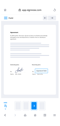
- the record and edit content using the Tools menu.
- Drag & drop fillable boxes, add text and eSign it.
- Include multiple signers by emails and set up the signing order.
- Choose which individuals will receive an executed doc.
- Use Advanced Options to limit access to the record and set up an expiry date.
- Click Save and Close when done.
Additionally, there are more enhanced capabilities available to warrant esigning. List users to your common work enviroment, view teams, and keep track of cooperation. Millions of customers across the US and Europe concur that a solution that brings everything together in a single unified work area, is what organizations need to keep workflows performing easily. The airSlate SignNow REST API allows you to embed eSignatures into your app, website, CRM or cloud. Check out airSlate SignNow and enjoy faster, smoother and overall more productive eSignature workflows!
How it works
airSlate SignNow features that users love


See exceptional results warrant esigning with airSlate SignNow
How to fill in and sign a PDF online
Try out the fastest way to warrant esigning. Avoid paper-based workflows and manage documents right from airSlate SignNow. Complete and share your forms from the office or seamlessly work on-the-go. No installation or additional software required. All features are available online, just go to signnow.com and create your own eSignature flow.
A brief guide on how to warrant esigning in minutes
- Create an airSlate SignNow account (if you haven’t registered yet) or log in using your Google or Facebook.
- Click Upload and select one of your documents.
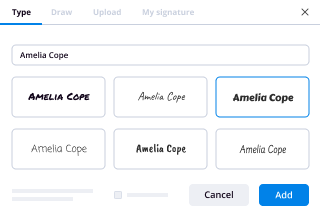
- Use the My Signature tool to create your unique signature.
- Turn the document into a dynamic PDF with fillable fields.
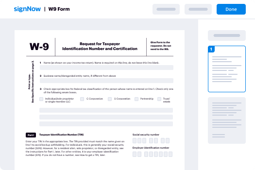
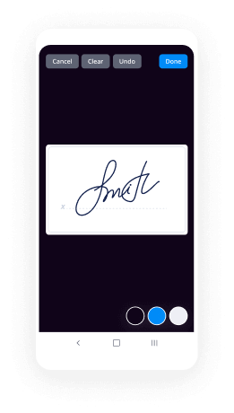
- Fill out your new form and click Done.
Once finished, send an invite to sign to multiple recipients. Get an enforceable contract in minutes using any device. Explore more features for making professional PDFs; add fillable fields warrant esigning and collaborate in teams. The eSignature solution supplies a reliable process and functions in accordance with SOC 2 Type II Certification. Be sure that all of your records are protected so no one can edit them.
How to eSign a PDF template in Google Chrome
Are you looking for a solution to warrant esigning directly from Chrome? The airSlate SignNow extension for Google is here to help. Find a document and right from your browser easily open it in the editor. Add fillable fields for text and signature. Sign the PDF and share it safely according to GDPR, SOC 2 Type II Certification and more.
Using this brief how-to guide below, expand your eSignature workflow into Google and warrant esigning:
- Go to the Chrome web store and find the airSlate SignNow extension.
- Click Add to Chrome.
- Log in to your account or register a new one.
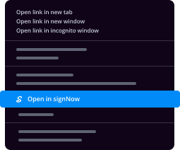
- Upload a document and click Open in airSlate SignNow.
- Modify the document.
- Sign the PDF using the My Signature tool.
- Click Done to save your edits.
- Invite other participants to sign by clicking Invite to Sign and selecting their emails/names.
Create a signature that’s built in to your workflow to warrant esigning and get PDFs eSigned in minutes. Say goodbye to the piles of papers sitting on your workplace and begin saving time and money for extra important activities. Selecting the airSlate SignNow Google extension is a smart convenient option with lots of benefits.
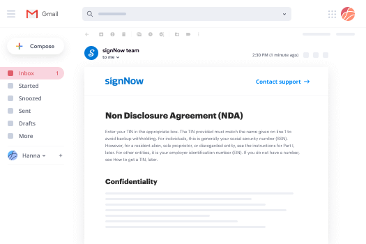

How to eSign an attachment in Gmail
If you’re like most, you’re used to downloading the attachments you get, printing them out and then signing them, right? Well, we have good news for you. Signing documents in your inbox just got a lot easier. The airSlate SignNow add-on for Gmail allows you to warrant esigning without leaving your mailbox. Do everything you need; add fillable fields and send signing requests in clicks.
How to warrant esigning in Gmail:
- Find airSlate SignNow for Gmail in the G Suite Marketplace and click Install.
- Log in to your airSlate SignNow account or create a new one.
- Open up your email with the PDF you need to sign.
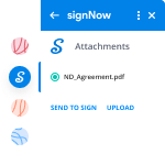
- Click Upload to save the document to your airSlate SignNow account.
- Click Open document to open the editor.
- Sign the PDF using My Signature.
- Send a signing request to the other participants with the Send to Sign button.
- Enter their email and press OK.
As a result, the other participants will receive notifications telling them to sign the document. No need to download the PDF file over and over again, just warrant esigning in clicks. This add-one is suitable for those who like focusing on more valuable aims as an alternative to burning time for nothing. Enhance your daily compulsory labour with the award-winning eSignature solution.
How to sign a PDF file on the go without an mobile app
For many products, getting deals done on the go means installing an app on your phone. We’re happy to say at airSlate SignNow we’ve made singing on the go faster and easier by eliminating the need for a mobile app. To eSign, open your browser (any mobile browser) and get direct access to airSlate SignNow and all its powerful eSignature tools. Edit docs, warrant esigning and more. No installation or additional software required. Close your deal from anywhere.
Take a look at our step-by-step instructions that teach you how to warrant esigning.
- Open your browser and go to signnow.com.
- Log in or register a new account.
- Upload or open the document you want to edit.
- Add fillable fields for text, signature and date.
- Draw, type or upload your signature.
- Click Save and Close.
- Click Invite to Sign and enter a recipient’s email if you need others to sign the PDF.
Working on mobile is no different than on a desktop: create a reusable template, warrant esigning and manage the flow as you would normally. In a couple of clicks, get an enforceable contract that you can download to your device and send to others. Yet, if you want an application, download the airSlate SignNow mobile app. It’s secure, fast and has an incredible design. Take advantage of in seamless eSignature workflows from your workplace, in a taxi or on a plane.
How to sign a PDF file using an iPhone
iOS is a very popular operating system packed with native tools. It allows you to sign and edit PDFs using Preview without any additional software. However, as great as Apple’s solution is, it doesn't provide any automation. Enhance your iPhone’s capabilities by taking advantage of the airSlate SignNow app. Utilize your iPhone or iPad to warrant esigning and more. Introduce eSignature automation to your mobile workflow.
Signing on an iPhone has never been easier:
- Find the airSlate SignNow app in the AppStore and install it.
- Create a new account or log in with your Facebook or Google.
- Click Plus and upload the PDF file you want to sign.
- Tap on the document where you want to insert your signature.
- Explore other features: add fillable fields or warrant esigning.
- Use the Save button to apply the changes.
- Share your documents via email or a singing link.
Make a professional PDFs right from your airSlate SignNow app. Get the most out of your time and work from anywhere; at home, in the office, on a bus or plane, and even at the beach. Manage an entire record workflow easily: make reusable templates, warrant esigning and work on PDF files with partners. Transform your device right into a powerful business instrument for closing contracts.
How to sign a PDF taking advantage of an Android
For Android users to manage documents from their phone, they have to install additional software. The Play Market is vast and plump with options, so finding a good application isn’t too hard if you have time to browse through hundreds of apps. To save time and prevent frustration, we suggest airSlate SignNow for Android. Store and edit documents, create signing roles, and even warrant esigning.
The 9 simple steps to optimizing your mobile workflow:
- Open the app.
- Log in using your Facebook or Google accounts or register if you haven’t authorized already.
- Click on + to add a new document using your camera, internal or cloud storages.
- Tap anywhere on your PDF and insert your eSignature.
- Click OK to confirm and sign.
- Try more editing features; add images, warrant esigning, create a reusable template, etc.
- Click Save to apply changes once you finish.
- Download the PDF or share it via email.
- Use the Invite to sign function if you want to set & send a signing order to recipients.
Turn the mundane and routine into easy and smooth with the airSlate SignNow app for Android. Sign and send documents for signature from any place you’re connected to the internet. Build good-looking PDFs and warrant esigning with couple of clicks. Created a perfect eSignature workflow with just your smartphone and increase your total productiveness.
Get legally-binding signatures now!
FAQs
-
How do I comply with the Esign act?
Step 1 - Availability of airSlate SignNow Delivery or airSlate SignNow Copies. ... Step 2 - Consent Choices. ... Step 3 - Consumer Actions. ... Step 4 - Hardware/Software Requirements. ... Step 5 - Affirmatively Consent. ... Step 6 - "After Consent" Disclosure. -
Will airSlate SignNow hold up in court?
In summary, electronic signatures are binding and will hold up in court so long as they can be authenticated. One way to ensure the authentication process is to use an electronic signature company such as airSlate SignNow, since courts have already ruled a signature using airSlate SignNow is presumptively valid. -
Is airSlate SignNow IRS compliant?
Overview. airSlate SignNow is a fully ESIGN Act compliant solution. All the IRS definitions and ESIGN law requirements are met by the core solution for all agreements sent through the service. ... Access to the configuration settings below requires an airSlate SignNow business or enterprise level of service. -
Can you sign contracts electronically?
The eSign Act states that signatures should not be denied legal validity solely because they are electronic, which means that a contract that is signed electronically can be brought into trial. However, a judge's willingness to accept that contract will depend on how the electronic document was signed. -
What does Esign stand for?
Related to ESIGN: Electronic signature. Acronym. Definition. ESIGN. Electronic Signatures in Global and National Commerce Act. -
Why was the E Sign Act passed by Congress?
The eSign Act: Passed by congress in 2000, the eSign Act provides a federal standard for all states to follow regarding electronically produced signatures on contracts. The Act established the rule that electronic signatures are as legal as hand-written pen and airSlate SignNow signatures. -
How can I Esign documents for free?
Choose a File to Sign. Choose the document you want to have electronically signed online. ... Set Signer Details. Register the signer's name and email address. ... Send for Signature. Your signer will receive an email requesting their signature. ... Sign and Download. -
How do I digitally sign a document?
Suggested clip How to Digitally Sign a document with airSlate SignNow Reader | Acrobat X ...YouTubeStart of suggested clipEnd of suggested clip How to Digitally Sign a document with airSlate SignNow Reader | Acrobat X ... -
What constitutes an electronic signature legally?
The U.S. Code defines an electronic signature for the purpose of US law as "an electronic sound, symbol, or process, attached to or logically associated with a contract or other record and executed or adopted by a person with the intent to sign the record."
What active users are saying — warrant esigning


Pass esigning order
hello everyone and welcome to another episode of MATLAB and Simulink robotics we know it was absolutely don't talk about an extremely fundamental concept in digital signal processing and that is filter design and to join me today I've got Marc Schwab from the engineering development group at the math works little mob you want to introduce yourself and tell us why you are the best person to talk to us about filter design all right come on up thanks for having me by the way um so I work as a application support engineer for math works and my domain is specifically signal processing and communication systems so a lot of the tools that we use in this video I use on a regular basis and many of my projects cool well welcome to the robotics arena ah so moving on today's agenda I'm gonna talk a little bit about the motivation as to why we decided to do this video in the first place following which Marc's gonna do a little bit of background on on filter design and go into the into the math involved with it and then we're gonna do a software demonstration and he's going to show us how to design a filter and then implement it in in in MATLAB and Simulink and we're gonna use the filter design tool for this and finally we could do some key takeaways and resources to have you guys do better at your competitions so sorry with the motivation marine robotics student competitions involve a lot of signal processing especially especially in the hydrophone task after home nation competitions like robot robot sub in robotics but before getting into you know into time direction what I will and all that kind of stuff you you need to start small and you need to start with with filter design by the way do have a video on on on finding the direction of arrival of the signal in MATLAB in the robotics arena so you might want to take a look at that so without further ado I'm going to hand it over to mark and have them have have them get into in the MATLAB and do some some background and and take it away so so before we get into the meat of this topic I'm gonna go over a little bit of background just to cover the basic mathematics behind filter design so when working with filters we're working with linear time-invariant systems and we have an input signal that's passed through the LTI system that contains an impulse or transfer function and then we receive an output signal in time the process that's being computed in the LTI system is called convolution and this is denoted by the first equation yeah convolution is not easy as you can see yeah the con the equation is quite complicated this definitely isn't ideal so a common practice in signal processing is to convert everything into the frequency domain and what this does is this converts the convolution process into multiplication which is much simpler so stop it at how we convert a signal from from the from the time domain to the frequency domain um to convert signal to the frequency domain we use the Fourier transform and in the software demonstration I'll talk a little bit about the tools that MATLAB and math works products provide you don't have to support this work okay so let's take a look at some of the fundamental filters perhaps the two most basic filters are the low pass and the high pass filter as implied by the name the purpose of the low pass filter is to preserve low frequency components and to attenuate or remove high frequency noise or unwanted high-frequency components conversely the high pass filter preserves high frequency components and attenuates low frequency components it's pretty simple - slightly more complicated filters would be the bandpass in the band stop filter the purpose of the bandpass filter is to preserve frequency components within a specific frequency range and then conversely the band stop filter attenuates frequency components within a specific range okay so what's up so these are pretty simple but pretty common filters in correct these are considered ideal filters so typically we may have idea filters um they're not the best choice for application I'm there more for analysis and in theory yeah they're more analysis in theory okay um so without further ado let's go ahead and jump into the software demonstration all right so the data that I chose to use here is actually data recorded from a submarine ping sensor from one of the robotics competitions okay all right so let's go ahead and load in this data real quick so in the workspace you can see what I'm loading in Y denotes the data that's why denotes the data that was recorded from the ping sensors and T denotes a time vector and then noise is the noise that we're gonna add to this signal to filter out and then duration is just the time of the signal just glad I did this noise is something that the Yelp mean that you're adding in just for the books of the demonstration right yeah for the purpose that demonstration I pretty much I generated a random number generator that creates random noise so there's the uncertainty in the hall today we're gonna talk and in real world you know it's hard to predict the noise it's gonna happen yeah this is supposed to mimic okay what application okay cool so let's go ahead and take a look at the recorded data in time as you can see there's three distinct pings that the hydrophone has the task of identifying correct so next we're going to add the noise that I mentioned to the signal and then compare the original signal in time the signal oh yeah I I cannot recognize a signal anymore it's just society noise this one yeah so as you mentioned the signal is almost indecipherable there's a little bit of correlation but even where they look slightly similar there is an amplitude offset okay so apart from converting convolution to multiplication analyzing signals in the frequency domain is also beneficial because it can make plots like this a little more clear so let's go ahead and convert the signal to the frequency domain as I mentioned before and see if we can get a better idea of how we can filter out some of this noise it just we do that this is this FFT function ease is is that the Fourier transform that you were talking about that converts you've got signals from time to frequency yeah in MATLAB FFT denotes the fast Fourier transform and will complete the task of converting the signals to the frequency domain for us okay so we're going to go ahead and convert both the original signal and the noisy signal into the frequency domain and then take a look at the two so we can compare as you can see analyzing the signal in the frequency domain gives us a really good idea of the significant frequency components from the original signal and where the noise is present pulses that we can see around 50 kilohertz and 125 kilohertz are the two main frequency components of the original signal and then the bands of dense frequency components are to note the noise you may be wondering why there's two distinct bands where the noise of present in robotics competitions there are pretty common there are pretty common sources of noise one obstacle that many competitors face is the noise generated by the motor of their own robots often distorts their information yeah and this would be denoted by the low frequency noise that lies within the abba range of 22,000 kilohertz and then the high frequency noise could be denoted by other robot sonar or other extraneous factors all right so let's uh let's jump into designing a filter and open the filter designer tool the filter designer tool allows you to design filters via radio boxes drop down menus and text boxes and all of these lie within specific components like the response type the design method the filter order frequency specifications etc okay and just going back to when you were talking about the background and I can see it's got the lowpass highpass bad possum and song but so so yeah we actually mentioned those those filters earlier in this presentation yeah and each one of these dropdowns are slightly more complicated methods to implement the low pass High Pass because as we mentioned ideal filters are not useful and are not useful in applications so there's slightly more intelligent look at filters provided okay also this tool implements several algorithms as you can see in the filter order the minimum order box is checked on this implements an algorithm that will generate a filter of the minimum order based on your specifications this tool also provides another feature that allows us to observe several different response types for the filter some of these response types are the magnitude response the phase response group delay phase delay impulse response step response and the pole-zero response there are several other options and if you're interested in learning more about them I'd recommend looking at the documentation for the filter designer tool so now let's see if we can go ahead and design a filter to attenuate some of the noise as I mentioned earlier our signal is being sampled at 300 kilohertz so let's go ahead and put that in and then since we're using a low-pass filter we're going to try to preserve some of the look frequency noise and attenuate out some of the higher frequency noise so taking a look at the plot of our noisy signal we can see that there's noise somewhere above 125 that 125 kilohertz so let's go ahead and set the pass band to be up to 125 kilohertz and then in real filter application square waves are not practical because the filter needs some time to drop down to the stop band so we're gonna need to give the filter a little bit of space to reach the stop band so let's give it around 2.5 kilohertz and set this one hundred and twenty seven point five kilohertz and then we'll design our filter okay so this this looks like a great filter now that we have the filter you may be wondering how do we actually implement this in that lab the filter designer tool provides the option for us to export the filter as an object to the workspace to do this you navigate to the file tab and then go to export a dialog box will pop up giving you a few options for simplicity we're going to export this as an object you can go ahead and keep the default name now I figured of the MATLAB workspace you can see we have an HD objects we have an HD filter object the way to implement this filter is to use the filter function as I mentioned we chose to export this as an object for simplicity because then then the filter function only replies the filter object as an argument and then the signal we're filtering and then for analysis we're going to convert this filtered signal into the frequency domain let's compare the original signal and time to our filtered signal and time so looking at this plot maybe our choice of filter parameters were not the best or maybe even our choice of filter is not the best so let's look at the frequency domain and see where we might have gone wrong so as you can see we did a good job of attenuating the high frequency components but almost as expected we still have that low frequency noise and then from the from the plot and time we see that the noise is still enough to drastically distort the signal okay so let's jump back into the filter designer tool and see if we can do a little bit better so a little fast the low-pass filter might not have been the best option because there's low frequency noise that we cannot remove from the noisy signal so let's see if we can try one of the slightly more complicated filters that we mentioned earlier so let's take a look at the bandpass filter since we were able to attenuate the high frequency noise successfully using the low-pass filter we're going to use the same parameters for the pass band in the stop band on the higher edge of our filter so let's pull up the frequency plot to see if we can identify parameters that will be successful in attenuating all of the noise looking at the noisy signal we can see that there are significant frequency components from the original signal slightly below 50 kilohertz and that the noise is within the audible range so it's probably somewhere less than 20 mm 22 kilohertz so let's go ahead and set the stop band to be a little over 22 kilohertz and again let's give the filter some time to rise to the passband so now we have a filter that looks like it will preserve a specific band um so let's export this filter workspace and see if this yields the desired result so when exporting variables if there's a variable of the same name you're gonna want to choose to override the variable or else you'll receive an area so let's export this and then jump back into our code and implement this new filter alright so looking at the signal in time it looks like we did a good job so let's go ahead and confirm that by again looking at the frequency domain in the frequency domain this looks great we have all the same significant frequency components from the original signal but perhaps we could even do a little bit better so let's go ahead and go back into the filter designer tool and take a look at some of those other analysis options that I mentioned earlier to see if this filter is actually optimal for our workflow so before maybe more on what's what's the first place and you'd start when you want to when you want to sort of look at making these videos better what is the what is the sort of first block that you go to so the pole-zero plot it's a very useful plot because we'll go ahead and take a look at all describe go over warrant so the posterior apply as much under the name provides the poles and zeros and this gives an idea of what the filter this gives us an idea of what the order of the filter is as you can see here there's 304 poles so that means that the order of 50 a stand that's not good yeah so that means the order of the filters 304 and for implementation and hardware that would use an unnecessary amount of memory so let's go ahead and see if we can change our filter a little bit to reduce the order as you can see the option for F IR is chosen in the design method F IR filters are more but are beneficial in the sense that they're theoretically simple bars are slightly more complicated slightly more complicated theoretically but this provides a better result in terms of filter order so let's choose the IR and see if this improves our filter oh yeah okay is 86 yeah yeah so now we see that the filter order is around 172 since we have 172 zeros so this is much better but this would still utilize a very large amount of memory so let's see if we can choose another type of IR filter to improve our filter even more for more information on these types of filter i'd recommend taking a look at our documentation I'm gonna go ahead and choose the elliptic filter as somewhat of an educated guess and then see what this does so now we can see that the filter orders around the magnitude of 20 which is much much better than the 304 we started with yeah so before we go on you didn't mention hardware implementations is that a weight that I could like add up you know deploy this this filter onto a hardware directly from MATLAB and Simulink or do I have to you know take these coefficients in and then write code for it standalone of course yeah so you mentioned MATLAB and Simulink I'm going to go ahead and start with MATLAB okay within the filter designer tool if you go to the targets pane okay yeah there's options to generate a code for several different hardware targets um there's also if we go back over to file the option to generate MATLAB code and correct from their code generation could be used to implement into filters okay um but we can also export to a cine link model yeah I mean just to see that this the the Simulink implementation but because I mean I know a lot of file he wasn't actually using Sibenik so you want to go ahead and show us how to do that and sure of course so I'm gonna go ahead and choose the export Simulink option and then click realize model if no model is currently open what this option will do is open a blank model with the filter block but I actually already have a model open that in terms a similar workflow to the software demonstration we just covered that yeah alright so as you can see a filter block was added to the to the model I already had open so before we go I'm gonna so I'm gonna go ahead and connect this block but before we move further I'll talk a little bit about what this model does the model reads in an input signal and then a noisy signal and adds the two signals together then these signals are passed through a filter and we can observe the output at all three stages through a scope coming down from the scope you can see a transformed subsystem I'm going to go ahead and click on that and take a little bit of time to discuss what's going on so the fast fourier transform is a process that's computed on a vector of information but Simulink runs on sample time so if we were to just simply implement the FFT block and simulate the the transform would compete would be computed for each sample time so we'd be taking the transform of scalars rather than vectors okay so what we do here is we use first use a zero order hold to ensure that our signal isn't this discrete time domain and then we use a buffer to store the signals into a vector in a vector so then we can use the Fourier transform so then of course like we did in MATLAB we take the Fourier transform and then take the absolute value two to analyze the data and then we use a special vector scope that's set to analyze the data in the frequency domain let's take a look at the results of the Simulink model to ensure that they're similar to the MATLAB code so first we'll take a look at the signal of time to the scope so as you can see it's clear that this is very similar to the signals that we had in my lab so let's jump over to the before the let's jump over to the signals in the frequency domain ensure that that's also so the vector since we have three different vector scopes there's going to be three different vector plots the vector scope does not support multiple inputs so we cannot stack plots like we did in the scope plot but as you can see again the the frequency the signal in the frequency domain also pretty strongly correlates the signals from from MATLAB okay cool if you'd like to follow the same workflow without using the MATLAB interface the digital signal processing toolbox also has a block used to generate digital filters to find this block let's go ahead and go into the library to find this block navigate to the DSP system toolbox choose filtering and then choose filter implementations and there will be a digital filter design block so let's go ahead and drag this into the model to use the digital filter design block double-click on the block and a graphical user interface identical to the one we used in MATLAB will be presented ok and in implementing this block you do not have to worry about exporting to City link when you click the design filter button those filter parameters will automatically be uploaded into your sending model as I mentioned earlier there's also the option to generate code for Hardware in Simulink to learn more about this i'd advise taking a look at the documentation alright so now let's go ahead and jump back to the presentation to look at some key takeaways so the filter designer tool allows for an iterative design and this is beneficial because in competitions the competitors likely won't know the parameters that they want to use their filter so they're gonna have to use a trial and error approach to really reach the best filter for their robot implementation for filter design is available on both MATLAB and Simulink and hardware implementation is also available on both platforms ok well thank you so much Bob for taking the time out to come and share this information with us before we wrap up for this video I'm just gonna go ahead and point you guys to some of these sources let me do always again we've got a lot of vide we were a lot of video content available and a lot more to come please write to us and tell us what you think about it and you can get in touch this either on our either at the robotics arena at math works comm or on our Facebook group and then also don't forget about the software offer we do offer free MATLAB and Simulink with the 70 odd products to student competition teams so please take advantage of that offer and you can you can get access to tools like the like the filter design interval and a bunch of other tools and finally we're also filling up the robotics section of the racing large blocks and don't forget to take a look at that as well and thank you so much for watching another episode on the robotics arena and we hope to see you again
Show moreFrequently asked questions
What is the definition of an electronic signature according to the ESIGN Act?
How can I eSign a form or contract in Word?
How can I sign a PDF file and send it back?
Get more for warrant esigning with airSlate SignNow
- Digital certificate signature service
- Prove electronically signed Merger Agreement
- Endorse digi-sign Weidel New Agent
- Authorize signature service Product Evaluation
- Anneal mark Delivery Order Template
- Justify esign Equipment Sales Agreement Template
- Try countersign Usage Agreement
- Add Development Agreement signed
- Send Freelance Web Design Proposal Template digi-sign
- Fax Birthday Party Invitation esign
- Seal Food Allergy Chart initial
- Password Catering Proposal Template signature
- Pass Stock Purchase Agreement email signature
- Renew Party Rental Contract digital signature
- Test Auto Repair Work Order electronically signed
- Require Deed of Trust Template byline
- Comment attestant countersignature
- Boost looker-on electronically sign
- Compel subscriber signed electronically
- Void Modeling Agency Contract Template template autograph
- Adopt Administration Agreement template digital sign
- Vouch Wedding Photography Quote template initial
- Establish Release of Liability Form template electronically sign
- Clear Coffee Shop Business Plan Template template countersignature
- Complete Summer Camp Fee Waiver template digital signature
- Force Photo Release Form Template template mark
- Permit Simple Cash Receipt template signed
- Customize Terms of Use Agreement template digi-sign